|
.jpg) SONY
SCD-1과 SCD-777ES SONY
SCD-1과 SCD-777ES
소니에서 1999년도에 SACD 포맷을 발표하면서 발매한 레퍼런스 시스템 중 SACD 플레이어가 SCD-1이며,
여기에서 발란스드 출력 등을 없애고 보다 저렴하게 출시된 모델이 SCD-777ES입니다.
 Super
Audio CD Super
Audio CD
SCD-1과
SCD-777ES이 다른 점은 아래와 같다고 알려져 있습니다.
| |
SCD-1 |
SCD-777ES |
| 발란스
출력 |
발란스 출력 장비
있음. 이 발란스 출력은 언발란스 출력으로부터 만들어 내고 있다. 발란스 신호를 만들어 내는 회로는 배면 패널의 뒤의 발란스
단자가 실려 있는 기판상에 있다. AD712에 의해 언발란스 신호로부터 정상·역상의 신호를 만들어 내 DC서보는 없게 콘덴서로
DC컷을 하고 있다. 발란스 출력은 배면의 스위치로 ON, OFF가능. |
없음 |
| 전원 트랜스 |
2개의 R코어 트랜스를 따로 따로 수지 봉인해, 쉴드
케이스에 넣고 있다. |
수지 봉인하고 있지 않다. 2개의 R코어 트랜스를 사용.
트랜스의 용량은 SCD-1과 같다. |
| 인슈레이터 |
5다리 지지. 면 접지 이지만, 내부에서 1점 접지
되고있는 편심 인슈레이타 |
4다리 지지. 통상의 면 접지의 편심 인슈레이타 |
| 프런트 패널의 형상 |
사이드 패널은 직선이 아니고, 프런트 패널과 접속하는
근처에서 좌우가 좁혀지고 있다. 이 때문에, 저면의 패널의 형상도 프런트 부분에서 좁혀지고 있다. 프런트 패널에 있는
SONY로고는 중앙에 위치해, 음각으로 되어 있다. |
CDP, DAT, MD 등 다른 ES시리즈와 통일감을
갖게한 디자인. 사이드 패널은 직선으로, 그대로 프런트 패널과 접속되고 있다. 저면 패널의 형상은 사각. SONY로고는 왼쪽에
있고 SCD-1과 같이 음각(SCD-777ES의 해외 모델의 검정색은 SONY로고는 음각이 아니고 붙어 있다). 표시창의
양측에는 세로에 홈이 들어가 있다. |
| 색 |
은색을 기본으로 해 사이드 패널은 푸른 색 |
일본 전용은 골드만, 해외 모델에는 검정색도 있다. |
| 톱 도어 |
은색. SONY로고가 음각으로 되어 있다. |
SONY로고가 인쇄 |
| 전원 스윗치 |
원형. SCD-777ES와 비교하면, 아래에 위치하고
있다. |
사각. SONY 로고 바로 아래에 있다. |
| 표시창 |
투명한 창의 부품은, 프런트 패널과 단차 없게 연결되어,
한층 더 전면에 돌출하는 형태가 되어 있다. |
프런트 패널의 뒤에서 프런트 패널의 단면을 통해 뚫고
나오는 형태가 되어 있어, 보다 프런트 패널의 알루미늄의 두께가 강조되는 디자인이 되어 있다. |
| 광학계 고정 방식 메커니즘 |
- |
메커니즘의 구조는SCD-1과 같다. SCD-777ES의
메커니즘에도 고정자 측에 사파이어 베어링, 스핀들 샤프트 측에 루비 볼이 사용되고 있다. 스태빌라이져도 같다. |
| 중량(카다로그 표기상의 값) |
약 27kg |
약 25kg |
| 그 외의 스펙 |
- |
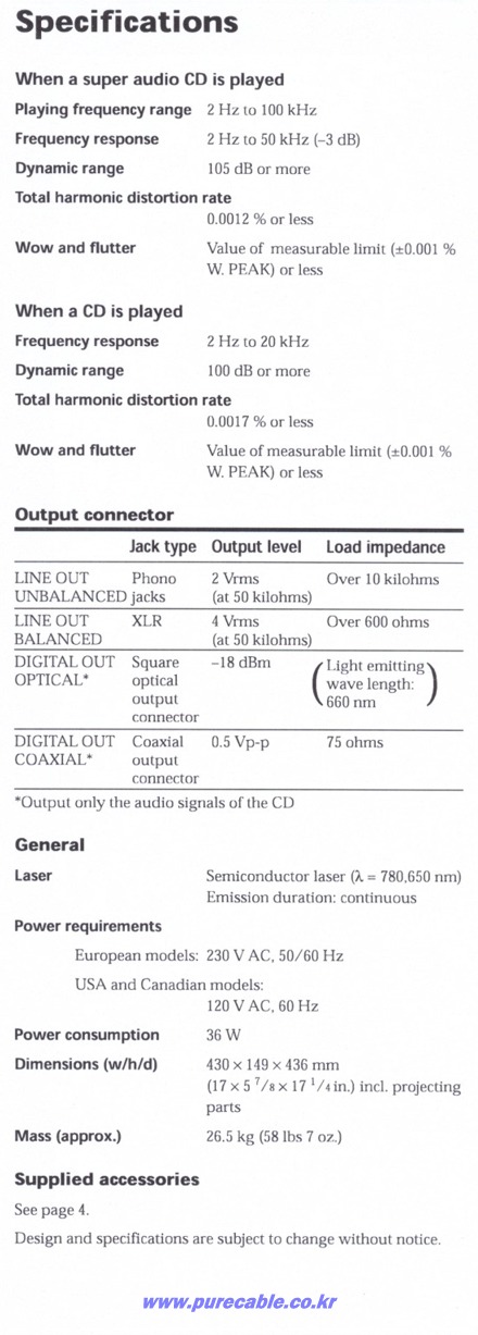
슈퍼 오디오CD 재생 시, CD 재생 시의 catalog
spec, 최대 외형 치수, 부속 리모콘은SCD-1과 같다. |
|

SCD-1

SCD-777ES
SCD-1 내부

SCD-777ES 내부

SCD-1 후면

SCD-777ES 후면
|
아래는 SCD-1에 대한 설명입니다. 여기
http://www.thevintageknob.org/SONY/sonyesprit/SCD1/SCD1.html 에서 보실 수
있습니다.
Super
Audio CD
|
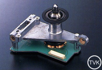
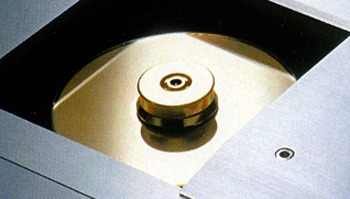
Fixed
Pickup Mechanism & Motor unit
Pickups are extremely sensible to noise, especially coming from the
servo current flow. Unfortunately, it is impossible to eliminate servo
current, as it is responsible for so many operations. Therefore, in
designing the SCD-1, we paid particular attention to creating a quiet
environment where pickup operation is not affected by servo noise and
thereby enable high precision readout.
The optical mechanism is fixed to the base unit. The optical pickup is
also fixed, eliminating its susceptibility to vibrations. For the SCD-1,
the disc itself is moved horizontally into position for the fixed
pickup. Compared to conventional systems, this system greatly reduces
the servo current influence on the pickup.
The system consists of two independent optical pickups combined in a
Twin Pickup System for reading SACD's 650nm wavelength and CD's 780nm
wavelength.

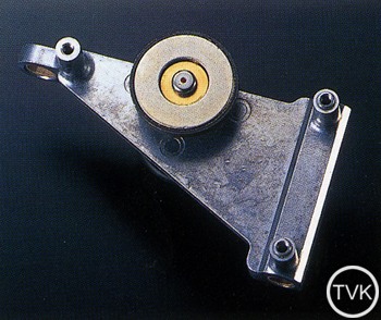
The
spindle motor is made of a newly developed die casting aluminum which
provides high rigidity. The stator side, the stationary portion,
includes the sapphire bearing, while the spindle shaft side, the spindle
axis, incorporates the ruby ball used in this bearing. This unique
combination of materials assures durability and reduces wear at the
contact point for very stable rotation. As a result of the increased
performance, servo current is decreased even further.
The entire mechanical block is floating, supported by four thick pillars
mounted directly to the chassis with a minimum of rubber damper.
The
mechanical base on which these parts are mounted on is made of a 6mm
thick, solid aluminum plate, which possess excellent rigidity for a firm
base. The cutout opening for the spindle movement is reinforced with an
extra plate to add to overall solidity. This plate includes openings to
eliminate metallic noise caused by vibrations.
The
chucking system is manual, featuring a high precision disc stabilizer
that is designed to match SACD's high-speed rotation.
|
|
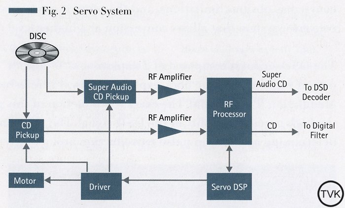
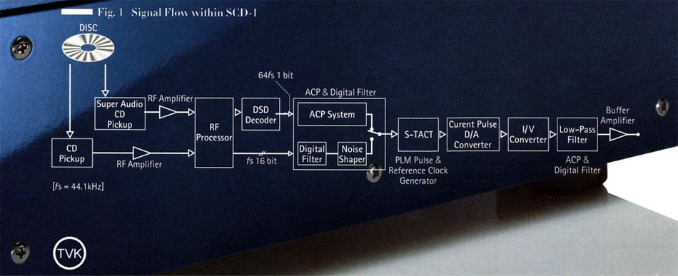
RF Signal Processing & Control Servo System
The
disc signals read by the optical pickup are amplified by the RF
amplifier set inside the mechanical block and then input into the RF
processor located on the main circuit board. This single RF processor
chip is responsible for clock signal extraction and synchronization, as
well as demodulation and error correction from the RF signals for both
CD and SACD. It is also responsible for the actual reading of the
information contained on the disc itself.
For
control of the optical pickup and motor systems, on the other hand, an
exclusive servo DSP LSI is used. Even though SACD is high density,
compared to conventional CD, scanning speed is increased threefold while
track pitch is halved, making the servo control systems for SACD and CD
very different. Thanks to a DSP used exclusively for the digital servo,
The SCD-1 attains the most accurate servo control for both formats,
achieving stable signal readout.
As mentioned earlier, using exclusive LSIs for digital processes like RF
signal processing and servo operation allows circuit boards to be
smaller and therefore reduce unnecessary noise.
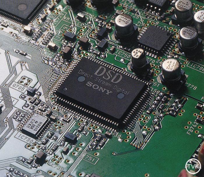
DSD Decoder
The
core of SACD's 1-bit signal processing is the newly developed DSD
decoder LSI. The RF processor merely extracts the data is contained on
the disc, without undertaking any analysis of the incoming data
whatsoever. The DSD decoder, on the other hand, has to make intelligent
decisions regarding processing of the incoming data and form the 1-bit
audio signal.
The DSD decoder first reads the watermark -a major feature for
protecting SACD from illegal copying- and then begins decoding of the
incoming signal. Using the memory, the intermittently output data is
rearranged and ordered according to the master clock from the audio
circuit board to be output in a continuous 1-bit audio data stream.
This LSI is also responsible for reading sub-code data such as TOC
information, including track number, time and text data.
 |
|
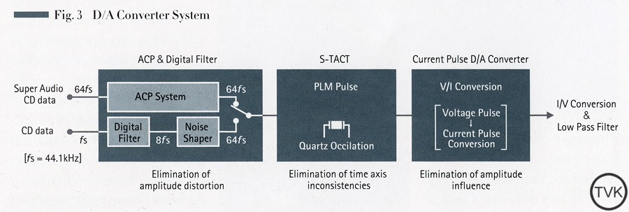
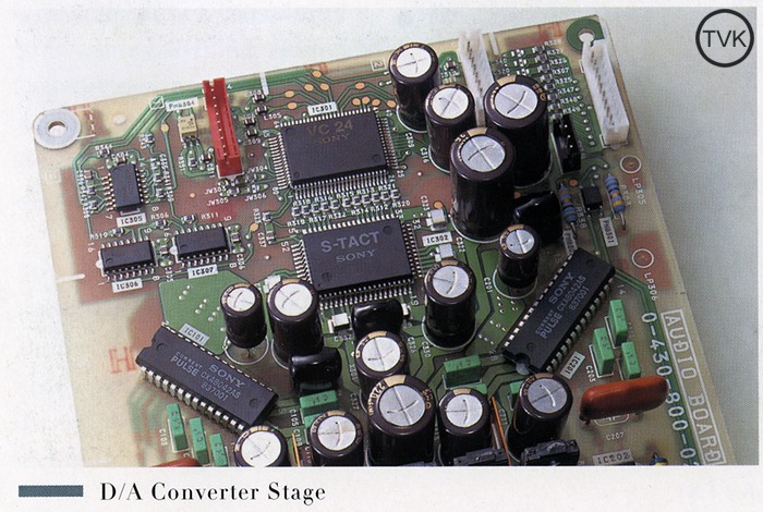
The D/A Converter System
In
principle, simply passing the DSD signal through an analogue low-pass
filter, it is possible to convert it back to an analogue signal. This of
course has obvious limitations, and therefore it was necessary to create
a new D/A converter system that allows conversion at a higher level of
precision than ever before.
The DSD signal is composed of 2 data values: "0" and "1". A "0" value
has no pulse output while a "1" value does, explaining why it is
referred to as a Pulse-density modulation(PDM) signal. The exact
reproduction of this pulse is vital for maintaining the high precision
quality of the DSD signal. The most important factors in determining
accuracy in pulse reproduction are:
> Precision of amplitude axis direction
> Precision of time axis direction
To
improve the precision of the amplitude axis direction, the ACP system
and a current pulse D/A converter were incorporated. And for refining
the precision of the time axis direction, an S-TACT pulse generator was
used.
 |
|
The D/A Converter System : S-TACT
The
Synchronous Time Accuracy Controller (S-TACT) pulse generator reads the
pulse code data and forms the pulse waveform accordingly. The pulse is
formed using the clock generator, which is controlled by a quartz
oscillator. For this reason, the pulse formed using S-TACT is extremely
precise, and therefore generally referred to as quartz precision.
Conventional systems incorporate digital calculating devices like a
noise shaper on the clock generator side. The SCD-1 completely separates
them in order to eliminate the influence from digital noise.
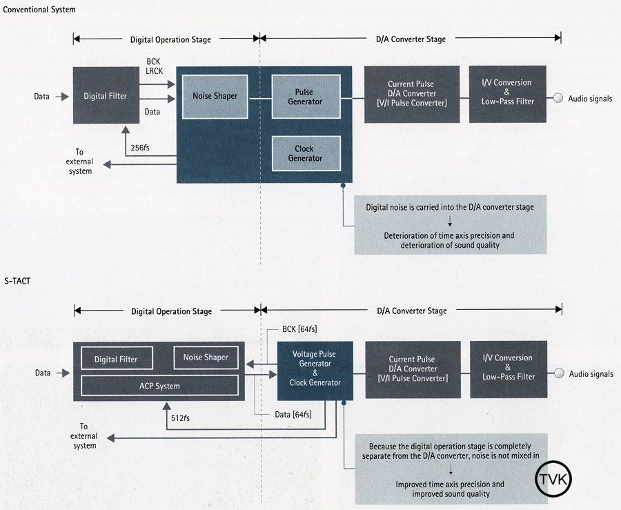
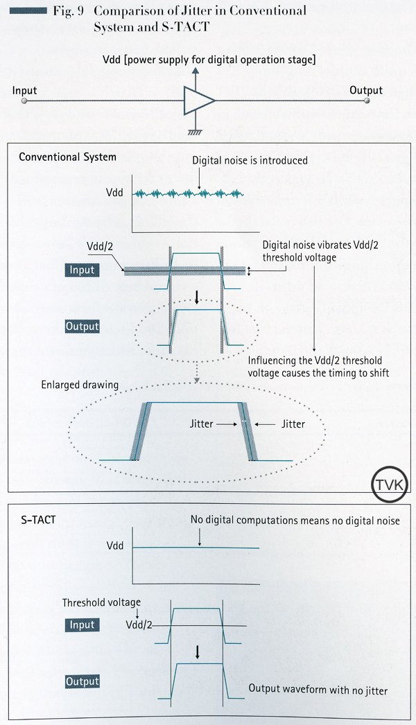
Signal processing carried out in the digital operation stage is
performed at a speed 512 time faster than the sampling frequency for CD.
This is equivalent to 8 times the sampling frequency for SACD. which is
performed at a capacity of over 50 bits. During these operations, the
switching noise emitted by the transistor element in the LSI IC is
considerable. The actual amount of switching noise is dependent on the
audio signal being processed. This noise enters the power supply and
creates voltage fluctuations, resulting in a loss of precision in the
time axis when the pulse is being formed. As jitter is introduced into
the pulse, the precision of the original signal is degraded.
S-TACT on the other hand, uses a discrete construction to completely
separate digital operations from pulse formation. As a result, it
becomes possible to create a pulse that achieves quartz precision for
the time axis. Making use of of this technology, SACD is able to provide
higher quality playback for improved audio software.
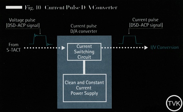
Current Pulse D/A Converter
The
current pulse D/A converter converts the voltage pulse output from the
S-TACT pulse generator into a current pulse. However, in the case of the
voltage pulse signal, the height of the pulse can be slightly affected
in the form of fluctuations during switching response. Taking this into
account, the SCD-1 incorporates a D/A converter for accurately
reproducing these pulse signals. Using an exceptionally stable and
constant power supply, the SCD-1's D/A converter converts voltage pulse
to current pulse and thereby enhances the precision of amplitude axis
direction.
 |
|
Advanced Capacity Variable Coefficient Digital
Filter
The
SCD-1 offers excellent playback performance for both CD and SACD
formats. The key feature for this high quality sound for the CD format
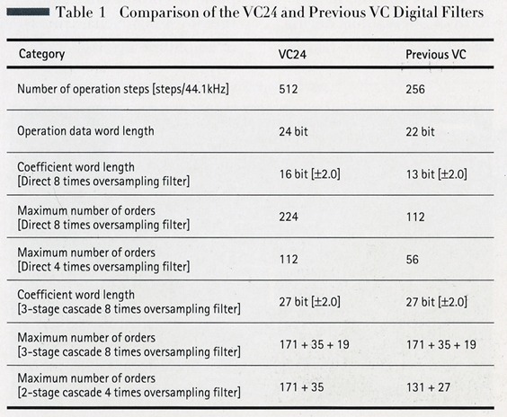
is the 24-bit precision variable digital filter (VC24).
Compared to conventional VC type digital filters, the VC24 handles twice
as many operation steps, has a 24-bit word length, as opposed to 22, and
performs direct 8 times oversampling at a 16-bit word length (3-bits
longer) all in one mode. Compare this with the number of bits which can
actually be processed within the allowed time span and the result is 2 x
2 x3 = 12 times the number of operation steps. Furthermore, when the bit
rate is represented in standard form, that is in a 10-digit system, 2
bit becomes 2²2 for 4 times the number of operation steps and 3 bit
becomes 2²3 for 8 times the number of operation steps. Therefore, the
total sampling rate is 2 x 4 x 8 = 64 times the number of operation
steps. This significant increase in in computing capacity over
conventional VC digital filters allows the VC24 to deliver improved CD
quality reproduction.
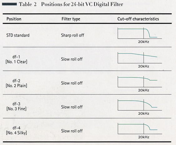
Conventional equipment generally uses a standard digital filter. And in
accordance with sampling theory, the fundamental principle in digital
audio, this type of filter abruptly cuts the band range over 20kHz.
The df-1 filter is responsible for
smoothing interpolation computations during 8 times oversampling. In the
past, because of limitations in computing capability, 8 time
oversampling was achieved by performing 2 times oversampling three
times. Thanks to VC24's capabilities, direct 8 times oversampling is
performed simultaneously. The result is smoother processing and therefore
cleaner sound quality.
The idea behind the df-2 filter is quite
simple. With the objective of being able to perform more sophisticated
computations than standard digital filters, as much as possible, the
df-2 takes the longest number for calculation processes. Conventional
filters have to use truncation (rounding to significant numbers) or
rounding up and down in order to pass the data on to the next stage.
Instead, the df-2 filter adjusts the length
of the input number to match the noise shaper in the next stage. This
way, all non-linear portions in the computation process are eliminated.
Thus, no quantization noise is generated and the data read from the CD
retains all of its integrity. Also, thanks to the direct 8 times
oversampling, there are no longer any non-linear computations between
stages, enabling powerful sound.
The df-3 is a completely new type of
filter. It is an even number digital filter with direct 8 times
oversampling and, by taking advantage of the VC24's advanced operation
capabilities, a 224-order filter. Even number filters use a completely
different computation process from conventional odd number filters. For
example, when performing 8 times oversampling, an odd number filter does
not process the original data read from the CD. Instead, it makes
computations using the interpolation data, which is a sample of 7.
In the case of this even number filter, computation processes are made
using the original data read from the CD and similarity using the
interpolated data from the 7 samples. Again, thanks too the VC24's
superior computing abilities, the 224-order filter enables flat
amplification characteristics from 0Hz to 17kHz, regardless of whether
it is a slow roll off type filter or not. Also, this filter enables
cutoff characteristics of over 26kHz and performance over 80dB, for
extremely high quality. The result is sound that is clear and full of
subtleties.
The df-4 position is based on df-2, with
performance enhancements. The computation word length is increased by 4
bits, and the filter degree is increased twofold. As with df-3,, it also
uses an even number filter. These specifications allow df-4 to achieve a
flat frequency characteristic up to 18kHz and a 20kHz gain. The df-4
reproduces fresh, energetic sound that is full of complexities.
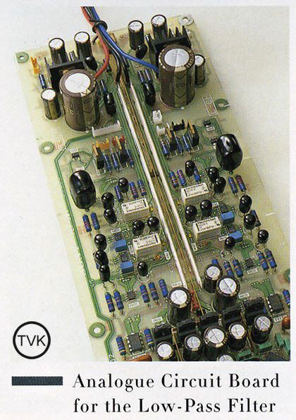
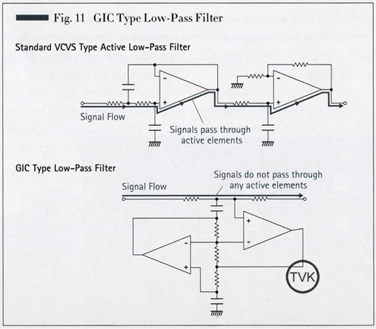
Low-Pass Filter
The
current pulse output from the D/A converter is I/V converted, and
finally passed through the analogue low-pass filter in the final stage
to become an analogue audio signal. The SCD-1 uses a GIC-type low-pass
filter, which is different from usual active-type in that the signals
are not passed through semi-conductors, or active elements, such as the
OP amplifier. This way, the GIC-type filter is able to maintain a high
degree of sonic integrity and pure sound quality.
In
the SACD system, playback frequency is not determined by the format.
Instead, it depends on the cutoff frequency and cutoff characteristics
of the low-pass filter on the player side. Therefore, maximizing
reproduction sound quality requires consideration of numerous factors.
Among them are the balance between increased bandwidth and the
elimination of quantum noise, as well as filter characteristics such as
circuit formats, number of stages, and finally, component element. [...]
Conventional amplifiers and speakers were designed using an approximated
20kHz frequency range characteristic. Assuming that the SCD-1 could be
used with such equipment, the frequency range in the standard position has been set to roll off
slowly at about 50kHz, creating a curve that satisfies DSD signals,
which are apt to exceed 100kHz. Combine the SCD-1 with the TA-E1 and
TA-N1 and, using the custom position, enjoy
an even more expanded frequency range.
 |
|
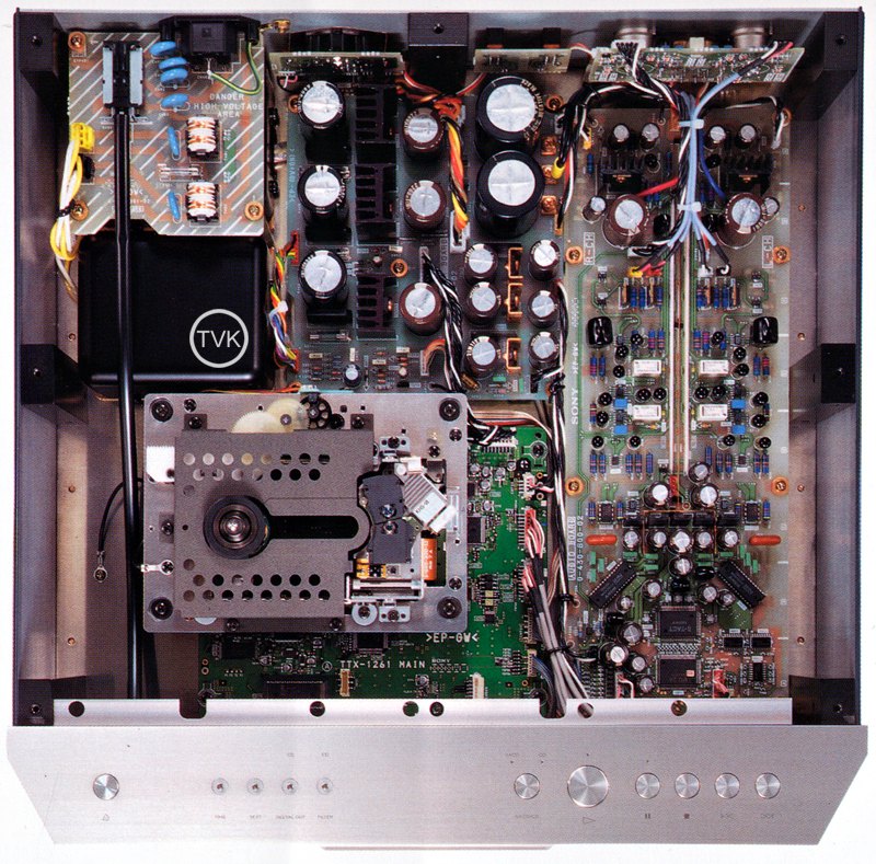
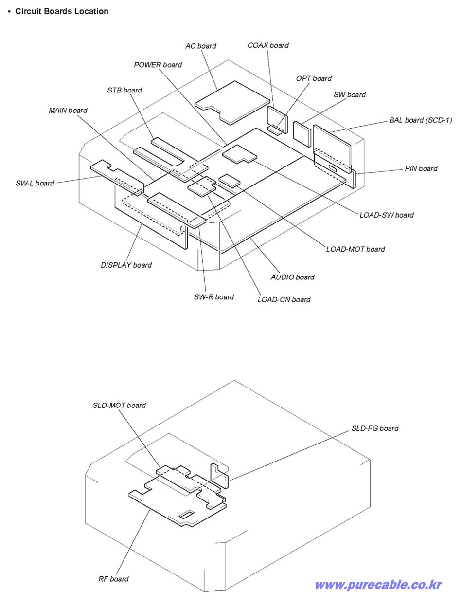
Ideal Circuit Board Layout
The
base of the circuit boards is made of a glass epoxy material with an
ideal pattern, incorporating a double-sided board, bus bar and a
symmetrical layout for the left and right circuit parts.
For the digital stage -which includes the VC24 and S-TACT- the goal is
to shorten the distance for data transmission and reduce noise by using
surface mounted parts. Furthermore, in the analogue stage after the LPF,
the incorporated lead parts -which possess superior sound capability - are
mounted with plenty of allowance. [...]
A discrete power supply block for the analogue stage is located on the
audio circuit board. By using separate circuits for the left and right
with an independent 3-layer bus bar, each block is able to achieve a
low-impedance power supply. The earth line was strengthened by directly
connecting the audio output terminal ground to the audio circuit board
using a thick copper plate. The output buffer amplifier is constructed
of discrete elements, and the output signals are therefore powerfully
driven.
The main circuit board, which handles digital processing such as servo
control, signal processing, and system control, incorporates a surface
mounting circuit board with 4-layer pattern construction. Thanks to
integrated mounting of LSIs and small-scale chips on each block,
complex, large-scale, circuits were successfully concentrated on one
small circuit board, referred to as a digital minimum circuit board.
Also, by placing the main circuit board under the mechanism block, the
signal from the optical pickup can be transmitted to the processing
circuit over the shortest possible distance, thus contributing to
reducing undesired radiation noise. The 2-stage construction of the
mechanism and the main circuit board allow the remaining area to be used
for arranging the other main blocks with plenty of allowance.
Furthermore, the power supply line and the signal line from the pickup
to the output terminals, are straight - an ideal layout for eliminating
unnecessary turns.
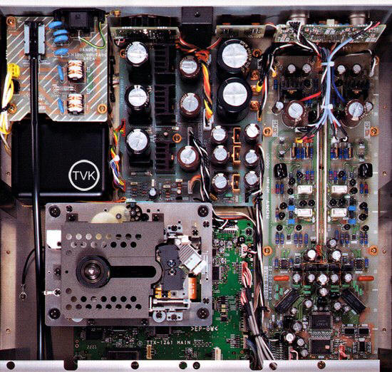
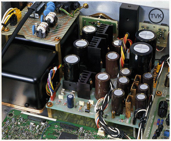
Power Supply Block
The
R-Core transformer is contained in a resin-sealed case which reduces
magnetic flux leakage and eliminates unwanted vibration. Two separate
transformers are included, one for handling the audio system and the
other for the servo and digital system. Also, the remote-operation type
power switch minimizes the intertwining of the primary AC power supply
line and thereby hinders power supply noise from entering.
The audio power supply circuit incorporates an individual component
construction. This discrete system is more effective at reproducing
high-quality sound. Also, mounting the audio power supply circuit on the
audio circuit board achieves a low-impedance power supply. Other
essential parts, such as electrolytic capacitors, were carefully selected
for their sound quality.
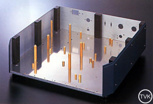
Base Pillar (BP) Chassis Construction
As
the first ever Super Audio CD Player, the SCD-1 features a revolutionary
innovation in its construction, including a new type chassis. In the
past, the strength of the chassis was accomplished by incorporating a
base and adding beams. The SCD-1's new simplified chassis structure
ignores all convention. The base chassis consists of two 5mm-thick metal
plates to create a rigid 10mm-thick base. On this base, seven high-carbon
cast iron pillars, 4,5mm-thick, slate blue side walls, and a 5mm-thick
top plate are mounted.
By using materials which are very themselves extremely rigid, a simple
but very rigid chassis and stable chassis was achieved. This new chassis
construction created a large, open space within the unit, enabling an
ideal layout for the different blocks.
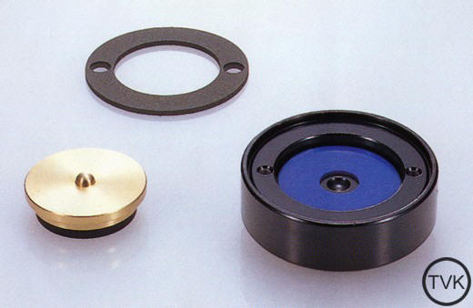
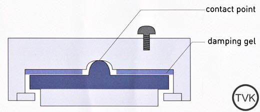
Insulating Feet
The
newly developed eccentric insulator feet is an off-center type that
offers two major advantages. First, the pin-point contact eliminates
resonance, or muddled sound, in the mid to high range. Also, the contact
surface area is perfect for reproducing heavy bass sounds. The base of
the insulator is made of a high-carbon cast iron, which offers high
attenuation characteristics. The inside of the base also uses the
pin-point system. The contact point is made two different metals, brass
and cast iron, for reproducing transparent sound in the mid to high
range. Using this combination of materials and part design, sound
quality was improved over a wide frequency range.
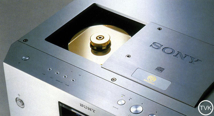
Disc Loading System
The
electric sliding-type loading mechanism moves horizontally, keeping the
guide rails completely concealed. The slide top rises slightly as it
slides smoothly to the side, and returns to its original height after it
stops. Such attention to mechanics is suitable to a product only of this
high quality. And for performance, the motor cover and floating mechanism
are insulated against noise and vibration, while the disc housing, where
the disc spins, is treated with anti-vibration coating. Also, the
contact point for the sliding mechanism is made of a high-carbon textile
with a Teflon coating to ensure sound insulation and high reliability.
Finally, the main axis for the slide mechanism is made of a stainless
material, and the bearing is made of solid brass for high rigidity.
|
|
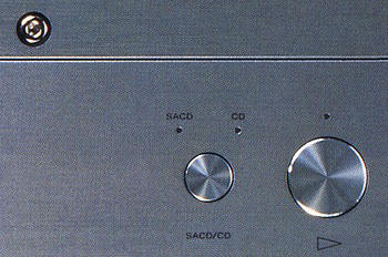
Disc Switching Button
The
SCD-1 automatically determines if the loaded disc is SACD or
conventional CD, and then begins playback. This is possible thanks to
the twin-pickup system. If playback selection is made in advance, the
identification time can be shortened. Also, for a hybrid disc, either
the SACD layer or CD layer, can be selected for playback.
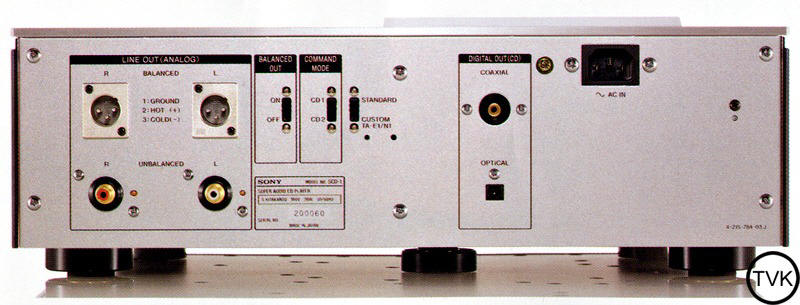
Digital Output
During CD playback, two types of digital output are possible: coaxial
and optical. Also, using the digital out button on the top panel,
digital output can be turned on and off. During SACD playback, there is
no digital output.
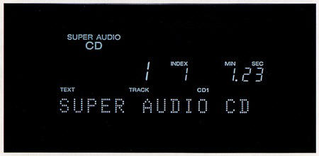
Display
The
SCD-1 incorporates a fluorescent character display. This large-size
display is able to show numbers up to three-digits long, allowing full
display of SACD discs, which can handle a maximum of 255 tracks or
titles. With the SCD-1, it is possible to enjoy over 100 songs with full
three digit display. Apart from the track and time display, there is a
15-character dot matrix message display area. Here, text data, unit
settings and warning indications are displayed. Using the DISPLAY MODE
button, it is possible to turn off a specific section or turn off the
entire display. The display window is made of thick acrylic material
with beveled edges. This, together with the half-mirror coating on the
inside provide a new and futuristic look.
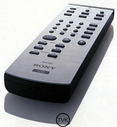
Remote Control
The
supplied, slim-type remote commander has a 1mm-thick aluminum top-plate
with buttons that feature a smooth click. [...] Filter settings and disc
types can be selected from the remote, too. The remote commander mode is
the same as for conventional Sony CD players, with code settings for CD1
and CD2. The Remote Commander setting and the Commander Mode on the back
of the SCD-1 must be set to the same code.
|
|
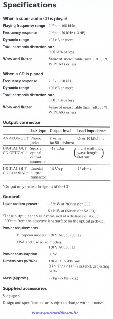
Specifications
|
SCD-1 |
SCD-777ES |
|
 |
 |
|
|